| |
Features:
•Fast Data Collection and Instrument Set Up: The operator
can select the frequency bands and the number of time series
stacks for data collection allowing optimization for data
collection. Typical data collection times of 10 minutes per
station and instrument set up time of 10 minutes per station.
•One-dimensional and Two-dimensional Field Plots:
Stratagem allows viewing of 1D soundings and 2D sections in the
field.
•Built-in Thermal Printer: Built in thermal printer can
print hard copy of time series, signal amplitude, signal phase,
coherency, apparent resistivity, resistivity curves, and depth
and frequency sections.
•Exploration as Shallow as 10 Meters and as Deep as 1 km:
Actual depth of investigation will vary with the ground
resistivity, signal quality, and whether low-frequency options
are employed.
•Complete Data Sets: Stratagem data file store complete
time series, cross-power data, spectral amplitudes, scalar
resistivity, tensor resistivity, phase, and coherency.
Configurations:
The Stratagem EH4 transmitter consists of a dual-loop antenna,
transmitter electronics, and controller. The transmitter
provides unpolarized source fields, which allow for true tensor
measurements of ground resistivities. This provides more
accurate interpretation of true resistivities than conventional
single-dipole transmitter source signals. The transmitter is
powered by a 12 V DC battery.
The illustration shows a typical configuration of the Stratagem
receiver. The magnetic fields are detected with two
perpendicular H-field sensors. The electric fields are detected
by measuring the differential voltage between the two electrodes
of the electric dipole. For example, the X-direction E field is
measured between Ex0 and Ex1 as shown in the diagram. The
response of the E-field sensors is amplified and filtered by the
Analog Front End and transmitted to the Stratagem console for
analog-to-digital conversion and digital signal processing..
The standard configuration provides for acquiring data in the
range of 10 Hz to 92 kHz. The low-frequency configuration will
allows the use of frequencies to as low as 0.1 Hz and thus
greater depth of investigation.
The standard configuration uses a small, portable
controlled-source antenna with a magnetic moment of
approximately 400 A-m2. For work in highly resistive areas there
is an optional large-loop antenna available of approximately
6,000 A-m2
Specifications:
Imaging System:
•Operating Principle: Natural and Controlled Source Tensor MT
•Frequency Range: 10 Hz to 92 kHz
•Transmitter: Model TxIM2 with Vertical Loop Antenna with
Frequency Range of 1 kHz to 70 kHz. Antenna Moment of 400 Amp-m2
from Two Perpendicular Vertical Loop Antennae Each 4 m3.
Operates on 12 V DC.
•Electrical Sensors: Four Model BE-26 Buffered Active
High-Frequency Dipole 26-Meter Cable with Four SSE
Stainless-Steel Electrodes
•Magnetic Sensors: Two Model BF-IM Magnetic Field Sensors (10 Hz
to 100 kHz) with 10-Meter Cables
•Analog Front End: One Model AFE-EH4 Unit for Analog Signal
Conditioning. Couples 2 Electric and 2 Magnetic Channels to the
Data Acquisition Package.
Data Acquisition Package
•Channels: Four (2E, 2H)
•Hard Disk: 1.2 Gbyte or greater
•Analog-to-Digital: 18 bit
•Digital Signal Proces: 32-bits floating point with bandwidth of
DC to 96 kHz
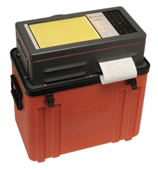
•Display: Liquid Crystal VGA
•Plotter: Built-in 4" (11 cm) wide plotter
•Power: 12 V DC, 40 Ah
•Operating: 0 C to +50 C in rugged portable/waterproof case
Options:
•Seismograph channels for integrated seismic measurements
Available with 12, 24, 36, or 48 channels.
•Magnetic Sensors:
Low-frequency 0.1 Hz to 1 kHz Sensors
|
|